You have no items in your shopping cart.
Construction Details
|
|
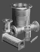
This website outlines selection and installation of our Metal Bellows type Expansion Joints and pump connectors for use in pipe lines and process vessels to absorb motion in the system. Our products incorporate the latest recommendations of the Expansion joint Manufacturers Association. |
|
Unaflex® is one of this country's leading Expansion Joint Manufacturers. Our expertise and manufacturing capabilities include a full range of Rubber Expansion Joints, Flue Duct, Expansion Joint Sound Absorbers, Custom Rubber Hose, Metal Hose, Pump Connectors an Metal Bellows Type Expansion Joints. No other manufacturer in the United States has the capabilities of Unaflex®. Unaflex® is a Full Service Manufacturing Organization offering a full range of products in the highest grades of stainless steel as well as more exotic alloys including Monel, Inconel and Hastalloy. Quality control is rigorous and complies with requirements of MIL-I-45208 and MIL-Q-9858. Our Expansion Joints also comply with U.S. Coast Guard requirements. Certification is available. |
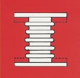
| CONSTRUCTION DETAILS BELLOWS PROFILE Unaflex® “MATCHLESS” Expansion Joint Bellows are produced from fully annealed type 321 stainless steel sheet stock rolled into a tube and seam welded. The latest technology in forming the corrugations of our bellows is employed. Other alloys such as Inconel, Monel, Titanium and 316 stainless steel may be provided from our extensive inventory or raw materials. |
 |
APPLICATIONS:
|
|
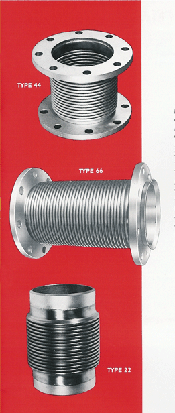
| A. Fixed Flanges Type 44 Ends are plate steel flanges conforming to ANSI dimensions welded directly to the integral ends of the bellows. Stainless steel and other alloys are available when specified. |
B. Floating Flanges Type 66 Ends are flat face plate flanges conforming to ANSI dimensions secured to the integral end of the bellows flared (Vanstoned) to retain the flanges. This allows the use of carbon steel flanges when the only wetted parts will be stainless steel of the bellows. Also permits easy bolt hole alignment. |
C. Welding Nipples Type 22 Ends are carbon steel welding nipples with ANSI standard bevel. Schedule 40 pipe size is used through 12” diameters. 1/4” wall thickness for sizes over 12” unless otherwise specified. |
|
DEFINITION OF MOVEMENT
|
|
|
AXIAL COMPRESSION
Reduction of face-to-face dimension measured along the axis. |
 |
AXIAL ELONGATION
Increase of face-to-face dimension measured along the axis. |
 |
TRANSVERSE OR LATERAL MOVEMENT
The movement of the joint perpendicular to the axis. |
 |
VIBRATION ABSORPTION
The movement of the joint due to vibrations which are effectively intercepted and insulated against transmission to remainder of systems. |
|
ANGULAR MOVEMENT
The displacement of the longitudinal axis of the joint from its initial straight line position (a combination of axial compression). |
|
ANCHORING AND GUIDING To assure satisfactory performance of an expansion joint in a piping system, it is imperative that the system be properly anchored and guided. Anchors must be designed to withstand the thrust forces, spring forces and guiding frictional forces of an expansion joint. Pressure thrust must be calculated by using the highest internal line pressure which the system will experience. This is frequently the test pressure. Spring force can be calculated from the expansion joint design data on pg 6-9 of out catalog.
*All information subject to change without notice. |
Click here to Request A Quote
or call us today at (866) 366-7604

