You have no items in your shopping cart.
STYLES 150 / 200 / 200XL
 |
Unaflex® "Supreme" Arch-type Expansion Joints are the WORKHORSE of our line. The arch design is the key that furnishes the flexibility required. Basic styles available in single, multiple or wide arch constructions are: styles 150 for pressure and vacuum, style 200 for Heavy Duty pressure and vacuum, and style 200XL for very high pressure service. Expansion Joints that handle up to 500ºF are available.
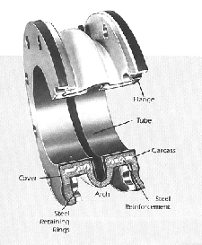
Basic construction consists of tube, flange, carcass, internal steel reinforcements, cover and steel retaining rings. Unaflex® Expansion Joints can be made with filled arches, multiple arches, Teflon® ( FEP) lined, sleeve ends, without arch, tapered (eccentric or concentric), offset, with enlarged arches and with special tube compounds for air, gas, oil, petroleum products, acids, slurries and chemicals of many kinds. Fire Retardant construction to ASTM F1123 specifications and readily available with complete testing and certification. All Supreme Expansion Joint constructions conform to U.S. Coast Guard requirements. |
|||||||||||||||||||||||||||||||||||||||||||||||||||||||
|
ALSO AVAILABLE IN TAPERED CONFIGURATION
|
||||||||||||||||||||||||||||||||||||||||||||||||||||||||
|
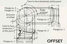
OFFSET
The degree of taper should not exceed 25º Where a taper is more than 15º, a filled arch is recommended. Where a filled arch is utilized, the available movement will be decreased 50% from that of an open arch. Where a proposed taper is greater than 25º, we recommend a steel reducer by utilized and a spool-type expansion joint be used in the adjacent piping. The above guides are generally applicable to concentric tapers. Where an eccentric taper exceeds 25º consult Unaflex® engineering department.
|
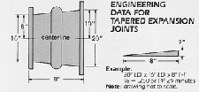
CONCENTRIC UNAFLEX® "SUPREME" Tapered Spool - Type Expansion Joints are available in three types: Style 150 for pressure and vacuum; Style 200 for heavy duty vacuum and pressure; and Style 200XL for extra high-pressure applications. Tapered joints are used to connect flanges with different diameters, whether parallel or offset, with initial misalignment less than 1/8 inch. Tapered joints can be made with the following variations: With filled arch, sleeve ends, without arch: with special tube materials; with larger arch; with straight section on smaller end of joint to assure clearance of bolts on eccentric type joints and on joints with considerable taper. Both concentric and eccentric shapes are available in a wide variety of sizes. As with the regular Expansion joints, when piping is not anchored, control units must be used to prevent over-elongation of the joints. For determining operating characteristic, use the largest I.D. dimension of the expansion joint for specifying refer to chart on "DIMENSIONS" page. ECCENTRIC NOTE:
|
|||||||||||||||||||||||||||||||||||||||||||||||||||||||
|
CONSTRUCTION DETAILS
|
||||||||||||||||||||||||||||||||||||||||||||||||||||||||
|
||||||||||||||||||||||||||||||||||||||||||||||||||||||||
| Style 150 - For Pressure / Vacuum service Style 189 - For High Temp and Low Spring rate, pressure limited to 25 Psi. Style 200 - For Heavy Duty High Pressure / Vacuum service Style 200XL - For very high pressures. Consult factory for construction details. Style1000 - Wide arch offers more movement. Hand wrapped build process offers a large variety of construction variations. Style 1100 - Wide arch offers more movement. Molded design keeps cost low. |
||||||||||||||||||||||||||||||||||||||||||||||||||||||||
|
CONTROL UNITS - Excessive elongation, caused by shifting of pipe lines, may seriously damage rubber expansion joints. This damage can occur when: necessary support is not provided for the weight of the pipe line; low temperatures in the line are encountered. the lines on the pressure side of air compressors are not anchored properly. Such destructive elongation con be controlled with UNAFLEX® control units. These units are recommended for use where such conditions occur, such as on air-conditioning units that are subjected to reduced temperatures. In general, control units are always recommended as an additional safety factor, preventing damage to the connector and associated equipment. Our experts will recommend the nits appropriate for your installation. |
||||||||||||||||||||||||||||||||||||||||||||||||||||||||
|
||||||||||||||||||||||||||||||||||||||||||||||||||||||||
|
SUGGESTIONS FOR INSTALLATION AND MAINTENANCE
|
||||||||||||||||||||||||||||||||||||||||||||||||||||||||
|
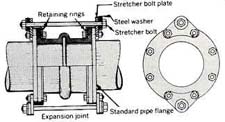
1. Clean all foreign matter and remove burrs or sharp edges from flanges. 2. All pipe lines should be properly supported, so that the expansion joints do not carry the pipe load. 3. Remove burrs or sharp edges from flanges 4. Do not install joints on raised face flanges of more than 1/16". 5. All pipes are to be lined up accurately before installing expansion joints. Offset joints should be installed where misalignment is greater than the lateral movement allowed by joint construction. 6. Paint flange face with a mixture of ordinary graphite mixed with enough glycerine to form a thin paste. This will assist removal if it should become necessary. 7. Bolts should be on the inside of the joint flange. Metal washer must be placed at the facing of the split retaining rings. 8. Bolts should be tightened by alternating around the flange and all tightened equally. 9. Slight gouges or abraded areas caused by tools or bolts during installation should be sealed with rubber cement and painted to prevent deterioration of the carcass. 10. Bolt tightness should be checked one week after going on stream and checked periodically thereafter. 11. Joints installed outdoors should have neoprene cover. All joints should be painted with Unaflex® Hypalon paint. 12. All joints should be painted with Unaflex® Hypalon paint once a year. 13. If system is not anchored to insure against movement beyond maximum stated limits control units must be used. |
||||||||||||||||||||||||||||||||||||||||||||||||||||||||
|
||||||||||||||||||||||||||||||||||||||||||||||||||||||||
Click here to Request A Quote
or call us today at (866) 366-7604